Printable Documents:
Click to Print Roton 780-224 Continuous Hinge Installation Instructions.
Click to print Roton Continuous Hinge Fire-Rated Installation.
Click to print Roton Continuous Hinge Electric Through Wire Installation.
Click to print Roton Continuous Hinge Electric Modifications Installation.
General Installation:
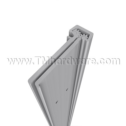
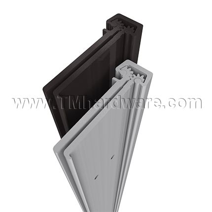
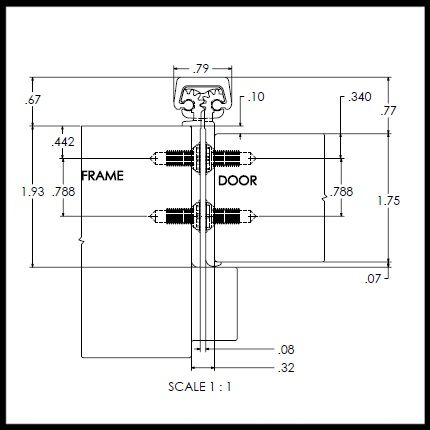
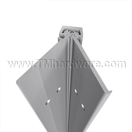
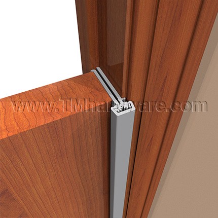
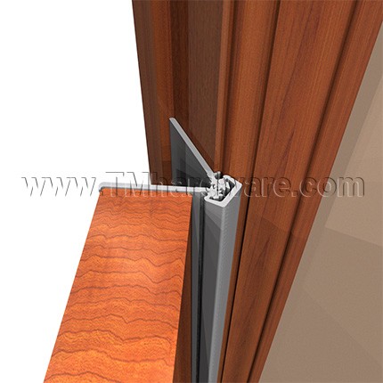
Roton Models 780-224 is an Aluminum Continuous Geared Concealed Leaf Hinge. This model provides a 3/32" door inset. The 780-224 can be used with any standard frame without hinge preps, and either with or without reinforcements depending on door weight. Clearance required between the hinge edge of the door and the frame rabbet is 5/16" minimum. 'HD" models have additional bearings for heavy-duty application.
Hinge Length:
All Roton hinges are supplied approximately 1" to 1 5/16" shorter than the nominal door height to avoid threshold or carpet clearance problems. If the hinge must be trimmed shorter, first determine the correct hand of the door and orientation of the hinge. Then mark and trim from the bottom of the hinge only - do not cut from the top end.
General Fitting Procedure:
- For new construction with metal doors/frames: To accommodate the 5/16" hinge clearance required for these Roton models, order the door undersized or the frame header oversized. See the clearance information above to attain the proper size. Mortar guards, either styrofoam or wood, are recommended for frames to prevent grout from interfering with the installation of the hinge fasteners.
- For new site-hung wood doors: If necessary, scribe and cut from the latch edge of the door to leave sufficient hinge stile thickness for proper fastening. A minimum clearance of 5/16" is required between the hinge edge of the door and the fraem rabbet. See the clearance information above to attain the proper finished width of the door.
- For remodeling with existing wood or laminate doors: If necessary, scribe and cut from the hinge edgeof the door and plane smooth. A minimu clearance of 5/16" is required between the hinge edge of the door and the frame. See the clearance information above to attain the proper finished width of the door.
Frame Preparation:
1. With the hinge open, place the hinge frame leaf against the frame rabbet making certain that the alignment rib is flush against the frame face along its entire length. Position the top of the hinge 1/16" (1/8" maximum) below the header. Note: A 1/16" shim is recommendeddue to initial settling of the bearings.
2. Mark and center punch the screw hole locations. Accurate location is important for proper installation.
3. For metal frames 12 gauge or less, it is not necessary to pre-drill pilot holes if using the self-dirlling screws provided. For metal frames thicker thatn 12 gauge, drill and tap all mounting holes for #12-24 threads prior to installing the screws. For wood frames, pre-drill pilot holes using a #18 bit for optional #12 wood screws.
4. Do not attach the hinge to the frame at this time.
Door Preparation:
1. With the hinge open, place the hinge door leaf against the edge of the door making certain that the door alignment rib is flush against the door face along its entire length. Position the top of the hinge flush with the top of the door.
2. Mark and center punch the screw hole locations. Accurate location is important for proper installation.
3. For hollow metal doors 12 gauge or less, it is not necessary to pre-drill pilot holes if using the self-drilling screws provided. For metal doors thicker than 12 gauge, drill and tap all mounting holes for #12-24 threads prior to installing the screws. For wood doors, pre-drill pilot holes using a #18 bit for optional #12 wood screws (provided with LL models).
4. Attach the hinge to the door. For metal doors, use the #12 self-drilling screws provided (recommended driver speed 1,900-2,500 RPM). For wood doors, use optional #12 wood screws.
Hanging the Door:
1. Position the door (with hinge attached) at 90 degrees to the frame. Attach the hinge to the frame rabbet. For metal frames, use the #12 self-drilling screws provided (recommended driver speed 1,900-2,500 RPM). For wood frames, use optional #12 wood screws.
2. Make a gentle trial swing. Carefully check the door for proper swing and clearance.
Adjusting the Door:
1. If lateral adjustment of the door is required due to excessive or uneven door/frame clearance, adjust by shimming where needed:
a. For minor adjustments, an effectiv shimming material is 1 1/2" cloth duct tape. Apply the tape in stepped layers underneath the frame leaf where needed to build up to the desired thickness.
2. To shift the entire door, a thin continuous aluminum strip may be used underneath the frame leaf (available in 1/16" and 1/8" thicknesses through our manufacturer).
3. Retighten all screws. Carefully check the door for proper swing and clearance.